Modeling
is a key stage in any software project, but it is crucial for large,
enterprise-class applications—exactly the class of applications that
keep companies up and running. A model is essential where complexity is
high. It helps to check correctness and adherence to specifications, and
it helps to build and maintain the software more easily. A clear and
well-designed model also helps developers—at any time—find the right
place to intervene to fix a bug. In software, a model should be viewed
the same as site maps, blueprints, and physical models in the
construction of houses: a definite need more than an optional tool.
Like
it or not, years of real-world experience demonstrate that large
projects normally exceed their budgets, their deadlines, or both. This
is just the real world, baby. Proper modeling is not a guarantee of
success for the project. However, it can be seen as your insurance
against a dramatic failure.
UML addresses this need
for an effective modeling language—a need that arose back in the early
days of object-orientated development.
1. Motivation for and History of Modeling Languages
The need for modeling
languages is tightly related to the broad adoption of the
object-oriented paradigm, which started in the early 1990s.
Object-orientation led developers to abandon subroutines and structured
programming and, instead, embrace a vision in which an application is
seen as a collection of interacting objects. Each object can receive and
send messages, process data, and invoke and control the behavior of
other objects.
Quite naturally, the
object-oriented paradigm led to devising systems as a web of related
components rather than as something that could be represented with
start-to-finish flowcharts. Describing and documenting the behavior of
such systems became harder and required appropriate tools and
methodologies for modeling.
1.1. UML Predecessors
In 1991, the need
for a modeling language produced Object Modeling Technique (OMT).
Developed by James Rumbaugh, OMT was a language for software modeling
and analysis. More or less at the same time, Grady Booch of Rational
Software (now part of IBM) created the so-called "Booch method," which
was an object modeling language and methodology tailor-made for
object-oriented design.
Around 1994, Booch, Rumbaugh, and Ivar Jacobson (the Three Amigos)
set up the group that unified different but related modeling languages
and methodologies into a single language. After that, an international
consortium—the Object Modeling Group (OMG)—was created under the
technical leadership of the amigos to formalize the Unified Modeling Language specification. This eventually happened in 1997.
Today, OMG governs the
development of UML and has more than 800 organizations associated as
members. You can learn more about OMG roles and initiatives at http://www.omg.org.
1.2. Versions and Standards of UML
Currently, there are two
main versions of UML, only one of which is officially ratified as an
international standard. Back in 2005, the International Organization for
Standardization (ISO) appointed version 1.4.2 of UML with the rank of a
recognized ISO standard with ISO/IEC 19501:2005. You can find out more about the UML ISO standard at http://www.iso.org/iso/iso_catalogue/catalogue_tc/catalogue_detail.htm?csnumber=32620.
Note
ISO
is an international organization whose primary goal is reaching a
general consensus on solutions that span an entire industry including,
but not limited to, the software industry. Usually, ISO doesn’t actually
define its own standards from scratch; rather, it draws on
specifications from other organizations. However, once ratified as an
ISO standard, a given specification is an effective standard worldwide.
This has been the case for UML (as of version 1.4.2) since 2005.
ISO/IEC 19501:2005
officially presents UML to the world as a graphical language for
visualizing, specifying, constructing, and documenting the artifacts of a
software-intensive system. As a result, today UML is the standard way
to write the blueprints for software systems.
Currently, the progress of UML within OMG has reached version 2.1.2. You can download the full paper at http://www.omg.org/technology/documents/modeling_spec_catalog.htm#UML. You should note, though, that this version has not been ratified as an ISO standard just yet.
So how does UML 2.x improve upon the previous, and standard, version?
In a nutshell, UML 1.x is a simpler language centered around the idea of modeling classes and objects. UML 2.x
goes beyond this threshold and adds the capability to present not only
behavioral models but also architectural models, as well as business
process and rules. With version 2.x,
UML ceases to be an object-oriented modeling language and begins to
target models used in other areas of the computing world and even in
noncomputing disciplines. UML 2.x reorganizes the contents of version 1.x
in a broader perspective and introduces many new tools, including new
types of diagrams. (We’ll say more about this in a moment.)
1.3. The Strengths and Weaknesses of UML
In the real world, nothing
draws criticism like recognized standards built from a generalized
consensus. It’s really hard to keep everybody happy. UML is no
exception. Although it is by far the most widely used modeling language,
UML lays itself open to criticism for being essentially a bloated
language. Not surprisingly, the ISO standard version 1.x was seen as needing improvement, and improvement came in version 2.x. Some people, though, now consider UML 2.x as being too bloated and complex as well as significantly harder to learn.
We feel that the strengths and weaknesses of UML descend from the U in the name, which stands for Unified.
In other words, UML attempts to be too many things to too many people.
Because of its declared generality, UML can be used in nearly all areas
of computing, but not always with the same effectiveness. The bottom
line is that UML generates a model, whereas working and functional code
is all that customers want—to start off, at least. Managing the gap
between the model and the code is up to the team, and that is the
natural habitat in which general criticism toward the language as a
whole springs up.
Initially, the U in UML had a positive overtone—unifying different, but similar, approaches to object-oriented modeling. Now, the U in UML is more the crux of the problem. To turn the general feeling about the U
back to positive, we should be able to easily and effectively restrict
UML to a particular domain. How can we easily transform a model into
another model without loss of information? How can we automa(g)ically
start working with UML and end up with code? If you look around, you’ll
see a number of ideas and some implementations, but no widely accepted
and adopted solutions.
Today, profiles in UML 2.x
offer a first formulation to adapt UML to a specific domain. Likewise,
the idea of programming on the UML diagram is precisely the vision
behind the model-driven architecture (MDA)—a design methodology launched
by OMG a few years ago. MDA is being talked about a lot, but it is not
yet in widespread use. A domain-specific language (DSL) is a possible
alternative to UML and MDA, as far as generating code out of a model is
concerned.
In summary, there are a
lot of good things in UML. In particular, UML is primarily a standard
language for modeling object-oriented systems through a graphical
notation. Based on this key milestone (essentially achieved with version
1.x), other features have been added to build a richer modeling platform. And here’s where most of the shades begin to appear.
UML should be conceptually split in two parts: U and ML.
A unified approach to modeling is welcome, but context-specific
modeling languages that are really close to implementation languages and
that have domain-specific expressivity are an unavoidable requirement.
Note
UML is merely a modeling language; it is not
a software development process. However, a few software development
processes exist that fully and rigorously integrate UML modeling
techniques. Examples are Agile Modeling and Unified Process.
1.4. UML in Practice
Abstractly
speaking, to use UML you need a methodology to gather and analyze
requirements and then a modeling tool to turn them into a designed
model. Usually, UML modeling tools incorporate their own methodology so
that, in the end, you just pick up the best tool for you. So, which
tool?
You
basically have two options—pick up a plain drawing tool that "does"
UML, or pick up a comprehensive tool that offers a team-based modeling
environment and embraces the full software development life cycle.
Microsoft Visio
Professional is certainly a tool that belongs in the first category.
There are several free, shareware tools and commercial tools that just
draw UML diagrams. A nonexhaustive list can be found at http://en.wikipedia.org/wiki/List_of_UML_tools.
In the second category,
we find tools such as Rational Rose XDE from IBM, Enterprise Architect
from Sparx Systems and, last but not least, Microsoft Visio for
Enterprise Architects. Microsoft Visio for Enterprise Architects is
included in MSDN Premium Subscription. It extends Microsoft Visio
Professional to perform round-trip engineering on software and
databases, thus enabling you to generate code from your UML diagrams and
generate databases from your database model diagrams. You can get the
same capabilities, and even more, from the other products mentioned,
which have different pricing models and scopes.
Note, though, that the round-trip engineering
description here is a bit emphatic and might look like an excerpt from
some commercial pamphlet. An effective implementation of round-trip
engineering is the key to effective use of UML in the real world. The
description here is definitely alluring; however, we admit the reality
might be a bit different. To understand why, we need to introduce
typical UML working modes first.
Note
Even though UML 2.x
is the current version of the language, not all modeling tools fully
support it. In particular, if you use Microsoft Visio Professional, you
might want to add some external stencils such as those from Pavel Hruby,
which are available through the Web site http://www.softwarestencils.com.
Note that these stencils and Visio vanilla stencils are mutually
exclusive. In addition, the Pavel Hruby stencils are purely graphics
tools and, unlike Visio standard stencils, do not perform any validation
of the model being created.
2. UML Modes and Usage
Over time, three modes of using UML have emerged and gained more or less wide adoption. They are referred to as sketch mode, blueprint mode, and programming language mode. Let’s dig out more details about each.
2.1. UML as a Sketch
We’re pretty sure that
every reader of this book, at least once in his or her life, has drawn
something on a paper napkin to record the basics of an idea. This is
pretty common among geeks, isn’t it? When drawing or writing on a sticky
note, a napkin, a whiteboard, or the back of a paid bill, you are
sketching an idea.
Note
Did
you know the venerable B-52 was in fact designed the evening before
Boeing presented it to the US Air Force, and it was designed on a
napkin? This is a true story. It still flies today, 50 years after its
design. Now this is exactly the difference between recording the basics
of an idea on a napkin and saving a napkin design!
"Section 2.1"
works in the same way, except that you sketch out a preliminary model
for a software system and commonly use a file rather than a piece of
paper. Used in this way, UML is merely a formal and visual language to
express and communicate an early and incomplete vision of the system.
Tools such as Microsoft Visio Professional and Microsoft Office
PowerPoint are commonly used to sketch out UML diagrams. (We have also
seen handmade UML-like paper drawings scanned to files and incorporated
in the project documentation as Microsoft Office Word files.)
"Section 2.1"
allows you to render incomplete diagrams with the simplest form—for
example, diagrams with limited details and covering only the principal
aspects of a system. More often than not, UML sketches are
collaboratively created by architects and developers during both
forward-engineering and reverse-engineering phases.
In general, forward engineering
is classic engineering—that is, an engineering approach wherein, to
build a system, you start by formally defining how it should be done and
how it should work. In forward engineering, you employ UML as the
language to express ideas to be shared and discussed. Through UML
high-level diagrams, you typically weigh alternatives, plan activities,
and assign tasks.
In general, reverse engineering
is when you take an existing system and figure out how it works. In
reverse engineering, you get a UML model out of the actual source code
of the system. The optimum situation is when the diagram you get from
reverse engineering matches the diagram you created with forward
engineering. Hitting this goal is the essence of round-trip engineering.
Do not be too surprised to see UML in action looking like the diagram shown in Figure 1.
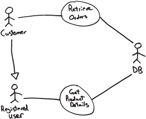
You
might reasonably wonder if there’s any benefit and added value in this
approach. At first, you might think that it is a waste of time or, worse
yet, clear evidence of poor professionalism. A sketched-out piece of
UML like the one in the figure clearly has no formal value, and we are not saying that we would present it at a formal meeting with the customer.
However, designing a
system is far too serious a thing to pretend you can sit down on day
one, have a look at standardized requirements, and start producing fully
detailed diagrams. As disappointing as it seems, things just don’t go
this way. In the early stages of development, using UML as a sketch is
highly productive because it provides a common, visual, and formal
language to express ideas and brainstorm about the design. Getting the
specifications of a system is an iterative process, and each iteration
might require creating a number of informal and approximate sketches,
whether drawn on napkins or saved digitally to a Visio or PowerPoint
file.
With a "Section 2.1"
approach, your goal as an architect is communicating information about
the system being created and gathering good input for developers to code
up. Using "Section 2.1" lets the proper design emerge
progressively and collaboratively, in an agile manner. To enhance
communication, you don’t need and don’t want to use UML at its fullest.
You need a formal language for sure, but one used in a more loose
fashion—just like sketches.
Note
On the topic of UML, we
gladly note Microsoft’s commitment to significantly improve UML support
in the next version of Microsoft Visual Studio. According to the latest
product Community Technology Preview (CTP), we’ll find a bunch of
designers for UML diagrams integrated into the next version of Visual
Studio, such as use-case, sequence, and class diagrams. Unlike Microsoft
Visio for Enterprise Architects, UML support in the upcoming version of
Visual Studio (codenamed Rosario at the time of this writing) will be
limited to modeling and separated from code generation. This switch
basically enables you to use "Section 2.1" scenarios in the next version of Visual Studio—a quantum leap in the right direction, we feel.
2.2. UML as a Blueprint
UML is as good at
brainstorming the system design (a sketch) as it is good at realizing a
formal and full description of the system that is ready for coders (a
blueprint). In any case, UML is the tool that architects leverage to
communicate with the development team.
"Section 2.1" and "Section 2.2"
are two distinct modes of using UML that refer to different views of
the design process. There are radically different philosophies
underlying each approach. With a "Section 2.2"
approach, your goal is to deliver a complete and exhaustive set of
specifications to the development team. You need to have a maximum level
of detail and accuracy in this type of UML diagram. The design is
essentially done entirely up front.
We like to summarize the differences between the two approaches by using the following contrasts: emerging vs. up front, or perhaps collaborative vs. ipse dixit. We also tried to capture these differences between "Section 2.1" and "Section 2.2" in Table 1.
Table 1. UML Sketches vs. UML Blueprints
| | UML as a Sketch | UML as a Blueprint |
|---|
| Philosophy | Emerging, collaborative | Up front, ipse dixit |
| Focus | Communication | Completeness of design |
| Goals | Help communicate ideas and alternatives about design choices, and focus on selected issues.
Iteratively come to a stable, but still incomplete, design of the system that is meaningful to developers. | Neat separation between design and coding.
Leave little or nothing to developer’s discretion.
Development must be a manual translation of UML into a programming language. |
| Level of detail in UML documents | Low | High |
| Formal value of UML documents | Low/medium | High |
| Tool | Lightweight designers, PowerPoint, whiteboards, napkins, backs of paid bills, and so forth | Ad hoc rich, specific, and often expensive tools |
In forward
engineering, the team first writes the UML blueprints and then produces
the related implementation code in the language of choice. Blueprints
should be detailed enough to leave as little as possible to the
developer’s discretion.
In reverse
engineering, a blueprint is generated from the source code to describe
the effective behavior of the system, typically in a graphical fashion.
With a "Section 2.2"
approach, you need a specialized modeling tool. Ideally, the tool
should assist the architect during the forward-engineering stage to
generate a set of detailed and unambiguous diagrams that are easy to
turn into code without open points and gaps for developers to fill.
Likewise, the tool should also be able to minimize over time the costs
of synchronization between the UML model and the software artifact.
Tools that support both forward engineering and reverse engineering are
said to be round-trip tools.
As you proceed with
coding and refactoring, it is crucial that you keep the UML model in
sync with the evolution of the code. As you refactor the code, you want
an updated UML returned that reflects your changes (reverse
engineering). The tool should provide this ability, and this is mostly
what makes "Section 2.2" tools extremely sophisticated and also expensive.
Does the "perfect" tool exist? This is hard to say.
For sure,
tools such as Rational Rose and Enterprise Architect give it a try and
do roundtrips. The tools vary in the way in which they store internal
information to sync up the model and the code. It is not unusual,
though, that after a certain number of roundtrips the chain breaks up
and you are left with the model and code out of sync. Manual
intervention to restore synchronization is then required.
For
sure, Microsoft Visio for Enterprise Architect does not provide much
help in this regard. For sure, the upcoming Visual Studio version will
not be of much help either, but probably for a different reason. In the
upcoming version of Visual Studio, the focus is on the "Section 2.1" approach.
Note
"Section 2.1" and "Section 2.2"
are based on different philosophies and have different goals. We
summarized this using the contrast of emerging vs. up front. This might
lead you to believe that the "Section 2.1" approach is agile and "Section 2.2"
is not. Agile is a methodology, and the project manager is responsible
for the methodology. A project manager can certainly require detailed
UML blueprints in the context of an agile methodology—and vice versa.
You can pick up a waterfall-like methodology and still communicate
sketched specifications to the development team.
2.3. UML as a Programming Language
The more you can come up
with a detailed model, the closer you get to a new programming language.
You have a formal, yet graphical, language and fully detailed behavior.
What really keeps you from compiling that source into executable code?
Nothing in theory. But, in practice, graphical programming is not manna
from heaven.
Can UML ever replace C#?
Or, better, will there ever come a day when you model your application
using UML and then just pass it on to a tool to generate code? Does this
really mean that all applications will be written in a fraction of the
time they take today?
Honestly, we currently
don’t think so. But we like the idea that this might be (effectively)
possible one day. Everybody has a secret dream, don’t they?
In a certain way, "Section 2.3" is just the next step past "Section 2.2." The highest hurdle on the way to "Section 2.2"
is the availability of tools that can perform loss-less roundtrips. A
second, and nearly as high, hurdle exists on the way to "Section 2.3": the absence of a UML graphical language with a pseudocode syntax.
We don’t know what the
future has in store, but in our humble opinion the general technology
outlook is not favorable for the success of a pure model-driven
architecture—the methodology that pushes the idea of using just UML as
your programming language. But we probably will get to use UML in a much
more powerful way than it’s used today and significantly reduce the
impedance between the model and the code artifact.
Note
OK, we just made a bold
statement about MDA here and took a clear and reasoned stand. Only those
who make predictions can make wrong ones. As the ancient Romans used to
say, "The future is held on Jupiter’s knees." So only time will tell.
However, if we’re wrong about MDA’s poor prospects for success, it will
likely be because of significant technical innovations. If MDA fulfills
its promise within a few years, we’ll be among the first to adopt it.
2.4. How We Use UML in Our Own Real World
So
we got to know the three main modes of using UML exist in the industry.
But what mode is the best? This is so hard to measure that we prefer to
rephrase the question for clarity and to avoid misunderstandings. So
what, in our humble opinion, is the best way to use UML? And how are we using it in our real-world projects?
We essentially iterate
through cycles of UML sketches up to the point of reaching a sort of
blueprint. More often than not, though, the blueprint is not as perfect
and detailed as it should ideally be. What we deliver as architects is
normally a model that is clear enough to communicate some key
architectural details and can be easily understood by developers. The
model contains at least the most significant use cases and class
diagrams. It doesn’t usually contain all possible sequence and activity
diagrams. Let’s say that we tend to put in all the most important
sequences, especially those for which we don’t want to leave any doubt
about the intended behavior. On the other hand, when you have
well-written use cases, the risk of creating a misunderstanding with
developers is really low.
What about reverse
engineering? Most of the time, we always end up keeping the UML and code
in sync through some doses of manual intervention.
Which tools do we use? Because we strongly believe in "Section 2.1," we stick to Microsoft Visio for Enterprise Architects. (And we are eagerly awaiting the next version of Visual Studio.)
Finally, some notes about UML in the industry. There’s a growing consensus in the industry toward using "Section 2.1." And the announced set of features slated for the next version of Visual Studio reflects this. We think that "Section 2.1"
delivers an excellent cost/benefit ratio—a good specification created
in a small amount of time, with no need to spend money to license ad hoc
tools.
In our experience, "Section 2.2" is a sort of chimera. And the same holds true for "Section 2.3"
and the related MDA approach. The UML we have today suggests that the
best we can do is sketch out models iteratively, reach a good
blueprint-like specification, and then start coding. This has worked
well for us to date.